
Your shopping cart is empty!
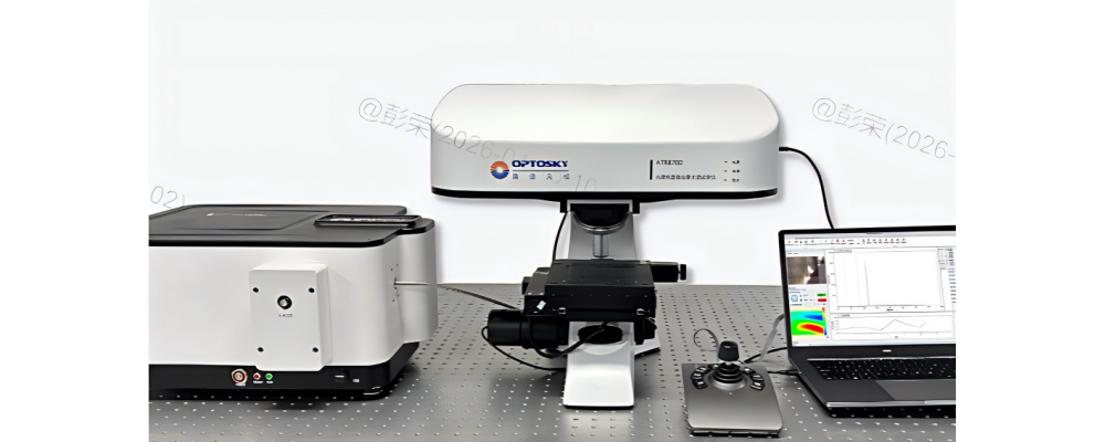
How to Assemble a Confocal Raman Instrument
Confocal Raman = sharper signals, cleaner spectra.By adding just one pinhole, we block out
of
focus stray light and fluorescence — unlocking micron
scale resolution and true depth sectioning.Better focus. Better data. Better decisions.Try it on your next micro
analysis.
Confocal Raman spectroscopy is a high
precision analytical method built on conventional Raman by integrating a confocal microscope optical path. By placing a confocal pinhole in the beam path, only the Raman signal from the sample's focal plane is allowed to pass through, effectively rejecting out
of
focus stray light and fluorescence. This enables micron
scale spatial resolution and depth
sectioning capability.
This technique is especially suitable for micro
areas, thin films, multi
layer interfaces, heterogeneous samples, and highly fluorescent systems. It also supports Raman imaging and 3D depth profiling. Confocal Raman has become a core characterization tool for "localization, micro
zone analysis, and phase identification" in materials science, minerals, biomedicine, polymers, and micro
contaminant analysis.
Below is a component
by
component guide to assembling a confocal Raman instrument.
1. Laser Excitation System (Energy Source)
Provides monochromatic, highly stable, narrow
linewidth excitation light, determining signal strength and the degree of fluorescence interference.
Laser options:
- 532 nm (green) – common for inorganic materials and carbon materials
- 633 nm (red)
- 785 nm (near
IR) – for biological samples and high
fluorescence materials
- 1064 nm – for strong fluorescence suppression
- UV options available for resonance Raman
- Multi
wavelength switching module for different sample types
Auxiliary components:
- Neutral density (ND) filters – adjust laser power to prevent sample damage
- Beam shaper / beam expander – optimize spot size and fill the objective back aperture for better focusing
- Shutter – controls exposure, protects the sample and detector
2. Confocal Microscope Optical Path (Core for Spatial Resolution)
Responsible for laser focusing, signal collection, and confocal spatial filtering — the heart of "confocal" capability.
Dichroic mirror: Reflects the excitation laser and transmits the Raman scattered light, separating incident and signal paths while maintaining coaxial alignment.
Microscope objective (critical component):
- High numerical aperture (NA 0.7–0.95)
- Focuses laser to a micron
sized spot and efficiently collects backscattered Raman light
- Determines lateral and axial resolution and collection efficiency
- Available in long / short working distance, dry / oil immersion, suitable for transparent or thick samples
Confocal pinhole (critical component):
- Micron
sized adjustable aperture located at a plane conjugate to the sample focal plane
- Allows only light from the focal plane to pass, rejecting out
of
focus stray light and fluorescence — enables 3D optical sectioning (Z
axis depth resolution)
- Pinhole diameter is matched to objective NA and wavelength, typically set to 1–2 Airy units
Imaging and observation components: White light illumination, CCD camera (brightfield / fluorescence imaging), eyepieces — used for sample positioning, morphology observation, and focus confirmation.
3. Filter System (Signal Purification)
Filters out the extremely intense Rayleigh scatter (same wavelength as the laser, 10⁶–10⁸ times stronger than Raman) while preserving the weak Raman signal.
Notch filter / Edge filter (core filtering element):
- Deeply suppresses Rayleigh light (OD > 6–8) and transmits Stokes / anti
Stokes Raman light
- Long
pass or notch filters for low wavenumber (<100 cm⁻¹) detection, suitable for low
frequency vibration analysis
Bandpass / short
pass filters: Further remove stray light and ambient background interference.
4. Dispersion System (Wavelength Separation)
Spatially separates Raman light of different wavenumbers to achieve spectral resolution.
- Monochromator / Spectrometer: Consists of an entrance slit, collimating mirror, diffraction grating (holographic / ruled — the core dispersive element), and focusing mirror.
- Grating line density (600 / 1200 / 1800 / 2400 grooves/mm) determines resolution
- Slit: Controls light throughput and spectral resolution; works together with the pinhole to optimize the signal
to
noise ratio.
5. Detector (Optical to Electrical Conversion)
Converts the dispersed Raman light signal into an electrical signal, determining sensitivity and detection range.
- CCD (Charge Coupled Device) – mainstream choice: multi channel, high sensitivity, low noise; suitable for visible light (532/633 nm)
- EMCCD (Electron Multiplying CCD) – for extremely weak signals and single photon detection
- InGaAs detector – suitable for near infrared (785/1064 nm); covers long wavelength Raman and suppresses fluorescence
6. Precision Sample Stage and Control System
- XYZ nano precision translation stage: Step accuracy <100 nm; enables point by point scanning (mapping), line scans, area scans, and 3D depth scans to generate chemical images.
- Auto focus and Z step module: Maintains confocal condition and acquires depth series data.
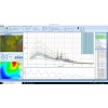
- Computer and software: Controls laser, wavelength switching, pinhole / slit, grating, detector, and sample stage; acquires spectra; processes data (baseline correction, fitting, imaging); exports results.
For more information, please contact:
Email: optoskyphotonics@gmail.com
Web: www.optosky.net
-100x100.png)
-100x100.png)

Search
Categories
Popular Posts


Latest Posts


Comments: 0
No comments